I'm getting ready to install an inverter that contains a built-in charger and xfr switch.
The inverter has multiple charge profiles for different battery types. I will eventually shift to lithium after the inverter circuitry is tested with the existing wet cells.
I read a post I really like about how they rigged up a 30A receptacle in their Class C electrical bay and merely plug the rig in when on battery/inverter power like it was shore power, knowing they can't run the A/C. I'm aware of that too and plan to manage my power use on inverter power (e.g. no toaster oven and micro at the same time).
They didn't get down in the weeds far enough in my opinion and never discussed how they deterred the infamous inverter/charger death loop.
I found a post on another forum that briefly mentions it. My question is how do I stop it with my setup. All these refer to separate charge controllers and xrf switches they turn down by flipping circuit breakers. I'm not seeing a similar option in my owner's manual.
I haven't found anything here, there or via Google to address my particular setup. I'm still researching this and may find something and want to include this forum in that effort. I'm almost certain others have done this?
I am a bit confused, not too amazing but, why would you have a "death loop" if the inverter you are installing has a built in charger? Simply disconnect the converter you presently have, not needed. When connected to AC power, the inverter transfers AC load to the shore power and charges the batteries. Lose the shore power and the inverter will power its loads from the batteries.... no charging if the original converter is disconnected.
I too do not understand the death loop. One thing you absolutely do not want to do is power the existing converter (if left installed) from your new inverter's output. This is mot definitely a death loop.
Do you have a single 30A shore power supply and a generator. How is the generator switched, by an outlet in the electrical bay that you switch the plug from generator to shorepower or an internal transfer switch. Tell us about that and then we can advise how to hook up your new inverter/charger.
If you leave the existing 12V charger in place then you have the 120V running off the inverter from the 12V batteries but the 12V charger running off the 120V is trying to charge the 12V batteries.
The simplest thing here is simply to turn off the breaker to the 12V charger when you're running off the inverter.
Except, of course, the inverter you're talking about has a built in charger and transfer switch. In that case you can completely remove the existing 12V charger and not worry about it at all.
In fact, since your inverter has a built in transfer switch you won't need the 30A plug at all: As soon as "shore power" goes away the transfer switch in the inverter will switch over (if you have the inverter turned on).
Thanks for the replies. I dont know if this helps anyone else so just throwing it out here. No one has to read it if they dont want to
I believe I have a solution and, like OldWeb suggested, the original xfr switch and converter/charger will be removed from the system and set aside for future consideration. I may remove it completely if the space proves useful for something else.
I have a question into AIMs. Well see if they answer. I dont have a copy of that message because its all online and I forgot to capture a copy. Ill replicate it best I can below.
The clincher in this setup was the 30A receptacle doesnt exist yet. and Id planned to install that in the electrical bay. If the invert is throwing 120 at the receptacle, I dont know the inverter has the logic to say Im outputting that juice, so its not really coming from a power pole. I believe it will interpret that 120 as shore power and say hey, the batteries are getting low, lets charge them. The problem here is the batteries are supplying the 120 so the inverter draws on the batteries to charge the batteries aka death loop or death spiral and the batteries are toast in no time flat.
Possible solution:
The inverter has a Charger Input Circuit Breaker. The current solution out there for whole-house power is to throw the existing charger circuit breaker, effectively removing it from the system. Most dont fool with the transfer switch. No need.
I believe I can simulate that behavior with the Charger Input Circuit Breaker and the steps in this process would be:
Inverter power:
1) open the Charger Input Circuit Breaker
2) plug the SP cord into the electrical bay receptacle
3) turn inverter on
Shore power:
Reverse the process with one extra step
1) turn inverter completely off
2) close the Charger Input Circuit Breaker
3) plug the SP cord into the power pole
4) turn the inverter on
In the shore power scenario, I dont want the initial connection power pole surge to harm the inverter, though dont know that turning it on manually will help much. I certainly dont think it could be any worse but Ive been wrong before.
In the inverter power scenario, I will have already disconnected from SP in some facility and rolled the cord up into the electrical bay.
Like I wrote, this may help someone else too so shoot holes in it if theres the opportunity. Id rather it turn into a piece of swiss cheese than cause someone heartache and expense (me included).
Thanks for the replies. I don’t know if this helps anyone else so just throwing it out here. No one has to read it if they don’t want to
I believe I have a solution and, like OldWeb suggested, the original xfr switch and converter/charger will be removed from the system and set aside for future consideration. I may remove it completely if the space proves useful for something else.
I have a question into AIMs. We’ll see if they answer. I don’t have a copy of that message because it’s all online and I forgot to capture a copy. I’ll replicate it best I can below.
The clincher in this setup was the 30A receptacle doesn’t exist yet. and I’d planned to install that in the electrical bay. If the invert is throwing 120 at the receptacle, I don’t know the inverter has the logic to say ‘I’m outputting that juice, so it’s not really coming from a power pole’. I believe it will interpret that 120 as shore power and say ‘hey, the batteries are getting low, let’s charge them’. The problem here is the batteries are supplying the 120 so the inverter draws on the batteries to charge the batteries – aka death loop or death spiral – and the batteries are toast in no time flat.
Possible solution:
The inverter has a Charger Input Circuit Breaker. The current solution out there for whole-house power is to throw the existing charger circuit breaker, effectively removing it from the system. Most don’t fool with the transfer switch. No need.
I believe I can simulate that behavior with the Charger Input Circuit Breaker and the steps in this process would be:
Inverter power:
1) open the Charger Input Circuit Breaker
2) plug the SP cord into the electrical bay receptacle
3) turn inverter on
Shore power:
Reverse the process with one extra step
1) turn inverter completely off
2) close the Charger Input Circuit Breaker
3) plug the SP cord into the power pole
4) turn the inverter on
In the shore power scenario, I don’t want the initial connection power pole surge to harm the inverter, though don’t know that turning it on manually will help much. I certainly don’t think it could be any worse but I’ve been wrong before.
In the inverter power scenario, I will have already disconnected from SP in some facility and rolled the cord up into the electrical bay.
Like I wrote, this may help someone else too so shoot holes in it if there’s the opportunity. I’d rather it turn into a piece of swiss cheese than cause someone heartache and expense (me included).
I'm pretty sure you are over thinking it.
If the inverter has a charger and a transfer switch built into it all that logic of "where is the 120V coming from" is already built in. You simply need to wire it up as the instructions say. No need for that extra 30a plug.
I'm guessing the instructions will say take the output of the transfer switch you already have (the one that sources 120V from either the generator or "shore power") and wire that into the inverter. Then wire the output of the inverter to your breaker panel. (Also wire the inverter to the 12V batteries.)
At that point you can turn off/remove the 12V converter since the inverter will do that.
Hmmm. I'd be glad to take this offline if you'd prefer. I just don't know how much anyone who cares would benefit doing it 'behind the scenes'.
I appreciate your offer to help solve this riddle and don't want to load you down with minutia but I attached the manual for your reference. It actually contains some of the logic in Boolean pseudo-code. If my inference correct, you know how to read it.
I too do not understand the death loop. One thing you absolutely do not want to do is power the existing converter (if left installed) from your new inverter's output. This is mot definitely a death loop.
Do you have a single 30A shore power supply and a generator. How is the generator switched, by an outlet in the electrical bay that you switch the plug from generator to shorepower or an internal transfer switch. Tell us about that and then we can advise how to hook up your new inverter/charger.
David
The gen output is treated the same as shore power and the xfr switch is triggered as though that was. You can here the switchover (click). My 'HOPE' is the inverter will sense the 120 from the gen and its internal xfr switch will behave the same way.
Yup I would put the inverter in between the RV's transfer switch and the breaker panel (output of RV's transfer switch goes to input of inverter and output of inverter goes to breaker panel).
No need to take this offline--this is exactly what these forums are for: To use the collective knowledge of the members.
Thank you. I mean that. I'm a bit confused. No surprise there. Please take home: this is not a contest and a need to draw upon the experience of others to the same or better result.
Assumptions:
1) you're staying with the 30A receptacle in the electric bay, somewhat implemented as previously stated with the following mods.
2) The OEM charger is completely out of the picture
3) when hooked to shore power, the OEM xfr switch output to the inverter's input negates the inverter xfr switch and the inverter's charger charges if needed.
4) when running on inverter power, the 30A receptacle trips the OEM xfr switch, tricking it into shore power, and negating the inverter xfr switch.
This is where I'm confused. Once the inverter senses it's hooked to 120, regardless of source, it's going to trip the inverter's charger. If that charging source is the batts, we're back in the loop unless the circuit breaker approach works.
What negates the inverter charger? Do I totally and wholly disable it at the via its circuit breaker?
If I don't negate the inverter's internal charger, it seems it will draw upon itself to charge the batteries - creating the loop.
I need some way of eliminating the inverter's interference or communicating I'm hooked to 'real' shore power, use that source instead of the batteries.
The box is solid state and this created a narrow way to deal with the setup.
I still do not understand why the proposed 30A receptacle in the electrical bay.
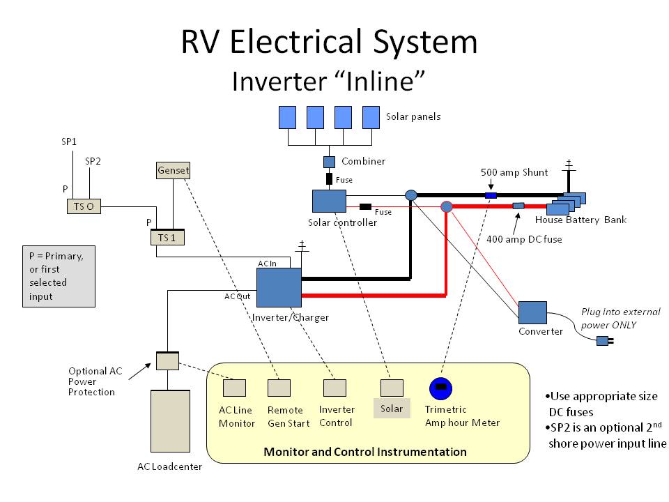
This diagram I borrowed from John Mayer and it includes a solar application for your Stage 2.
This application is for a 'whole house' inverter, where everything AC will be powered by the inverter. The only "odd" item I see is there are two shore power cords (for his 5th wheel by what I understand), you only have to use one. There is also shown the OEM converter... it is there to only be connected externally, to eliminate all confusion, like an emergency back-up.
So when you have AC power from either the SP cable plugged into a pedestal or the generator is running, the TS1 transfer switch (OEM) will supply the inverter. The inverter will use that AC and
1) Convert the AC to DC for charging the batteries.
2) Bypass the inverter part with its internal transfer switch and supply the RVs AC breaker panel.
Now, if the TS1 fails, there is no generator power AND/or the shore power cable has no AC to it, the inverter will do its job.
1) No AC to the input of the inverter, the inverter now turns off the battery charger (internal)
2) The internal inverter transfer switch connects the inverter part to the AC breaker panel
3) The inverter starts humming and supplies pure sine wave power (in your case).
Maybe the John Mayer link will help. So why the 30A receptacle?
Thank you. I mean that. I'm a bit confused. No surprise there. Please take home: this is not a contest and a need to draw upon the experience of others to the same or better result.
Assumptions:
1) you're staying with the 30A receptacle in the electric bay, somewhat implemented as previously stated with the following mods.
2) The OEM charger is completely out of the picture
3) when hooked to shore power, the OEM xfr switch output to the inverter's input negates the inverter xfr switch and the inverter's charger charges if needed.
4) when running on inverter power, the 30A receptacle trips the OEM xfr switch, tricking it into shore power, and negating the inverter xfr switch.
This is where I'm confused. Once the inverter senses it's hooked to 120, regardless of source, it's going to trip the inverter's charger. If that charging source is the batts, we're back in the loop unless the circuit breaker approach works.
What negates the inverter charger? Do I totally and wholly disable it at the via its circuit breaker?
If I don't negate the inverter's internal charger, it seems it will draw upon itself to charge the batteries - creating the loop.
I need some way of eliminating the inverter's interference or communicating I'm hooked to 'real' shore power, use that source instead of the batteries.
The box is solid state and this created a narrow way to deal with the setup.
Thanks again for your interest and feedback.
What you'll have is two transfer switches in a row, they don't negate each other.
When connected to shore power you have 120VAC going to the coaches xfer switch which will select that and route that to its output.
That output is going to the inverter's input. The inverter will sense that there is 120VAC on its input and its transfer switch will route that directly to the inverter's output lines.
When the generator is running the coaches xfer switch will route that to its output (the input to the inverter). Like on shore power the inverter's xfer switch will sense 120VAC on its input lines and route that directly to its output lines.
When neither generator nor shore power is connected/running the coaches xfer switch outputs nothing and the xfer switch in the inverter does not detect 120VAC on the inputs and thus turns on the inverter and routes its output to the 120VAC output lines.
The inverter's charger will only charge the battery(ies) when it detects 120VAC on the input lines (and use that to charge the battery(ies) by back feeding 12V on the wires connected to the battery(ies) ).
The coaches charger can be disconnected as it isn't needed.
Thank you for taking time out of your day to thoroughly explain all this to me. I hope I'm not the only one getting something out of all your effort. Believe it or not, it's actually starting to sink into this thick head of mine.
I need to sit with this thread for a time and take it all in. Thanks again and enjoy the rest of your weekend.
I still do not understand why the proposed 30A receptacle in the electrical bay.
This diagram I borrowed from John Mayer and it includes a solar application for your Stage 2.
This application is for a 'whole house' inverter, where everything AC will be powered by the inverter. The only "odd" item I see is there are two shore power cords (for his 5th wheel by what I understand), you only have to use one. There is also shown the OEM converter... it is there to only be connected externally, to eliminate all confusion, like an emergency back-up.
So when you have AC power from either the SP cable plugged into a pedestal or the generator is running, the TS1 transfer switch (OEM) will supply the inverter. The inverter will use that AC and
1) Convert the AC to DC for charging the batteries.
2) Bypass the inverter part with its internal transfer switch and supply the RVs AC breaker panel.
Now, if the TS1 fails, there is no generator power AND/or the shore power cable has no AC to it, the inverter will do its job.
1) No AC to the input of the inverter, the inverter now turns off the battery charger (internal)
2) The internal inverter transfer switch connects the inverter part to the AC breaker panel
3) The inverter starts humming and supplies pure sine wave power (in your case).
Maybe the John Mayer link will help. So why the 30A receptacle?
Thank you very much! Sorry fat-fingered the initial reply.
The 30A receptacle is likely not necessary if I can get in front of the where ever the existing 120 sources are input. I just thought it safer and easier to use the receptacle and let the systems behave somewhat normally, given the charger has to come out of the loop, by hook or by crook. Connecting directly to the AC bus may be an option and something I should strive to better understand.
I
...cut...
The only "odd" item I see is there are two shore power cords (for his 5th wheel by what I understand), you only have to use one. There is also shown the OEM converter... it is there to only be connected externally, to eliminate all confusion, like an emergency back-up.
I think I found you an answer. It's on his page under Note 1:
"Note 1
Optionally, I show two main shore power cables. When using an external generator (either portable or truck mounted) it is often convenient to have a shore power cable at the front of the rig. You simply use another 50-amp transfer switch - that way you can't have both "live" at once, or energize the other plug. This is obviously optional, but when wiring the transfer switches and deciding where to break into the main shore power cord you might consider leaving enough slack in the line to accommodate a future transfer switch if you decide not to do this right away."
I read what people share. I have the most skin in the game so it's on me to do my homework and complete my reading assignments
What you'll have is two transfer switches in a row, they don't negate each other.
When connected to shore power you have 120VAC going to the coaches xfer switch which will select that and route that to its output.
That output is going to the inverter's input. The inverter will sense that there is 120VAC on its input and its transfer switch will route that directly to the inverter's output lines.
When the generator is running the coaches xfer switch will route that to its output (the input to the inverter). Like on shore power the inverter's xfer switch will sense 120VAC on its input lines and route that directly to its output lines.
When neither generator nor shore power is connected/running the coaches xfer switch outputs nothing and the xfer switch in the inverter does not detect 120VAC on the inputs and thus turns on the inverter and routes its output to the 120VAC output lines.
The inverter's charger will only charge the battery(ies) when it detects 120VAC on the input lines (and use that to charge the battery(ies) by back feeding 12V on the wires connected to the battery(ies) ).
The coaches charger can be disconnected as it isn't needed.
I sat with this for a while and think I found what gave me pause.
If I run the inverters AC out to the 30A in the electric bay, it's going to look like 120. This is where your xfr switch assertion plays out.
The inverter isn't going to care where the 120 is coming from. I think there's an assumption that the inverter knows it's the one supplying the 120 via the batts and won't try to charge the batteries.
If I take the simplistic view, the inverter doesn't care where the 120 is coming from, only that's it's there, and will function as though the source is SP or gen. The problem starts when it's neither and it's the batteries.
If 120 looks like 120, regardless of source, then the inverter will try to charge the batteries when they're low, drawing upon the batteries to do that. Hence, the loop. I have not seen anything in the manual that cites, 'The inverter won't try to charge the batteries if it's running from the batteries.
You and I would think that's just logical and should be automagically included in the boards logic: 'Hey, I'm creating the 120 by pulling on the batts. Don;t be a fool and try to charge the batts'. I think that's a dangerous and possibly costly assumption (IMHO).
If I'm truly hooked into another source (i.e. SP or gen), then I do see where your explanation hits home. My going in understanding remains at:
1) Inverter takes 12V and creates 120V
2) AC is wired to electric bay receptacle
3) 120 shoots through both xfr switches to the inverter
4) Inverter supplies 120 AC as it normally would
5) Inverter senses batts are low and attempts to charge them
I have my loop and I'm back to square 1.
I have not heard back from AIMs yet and will update this with their response if received. Other than a solid response from them, I think I'm safer just hitting that CB and making sure it doesn't see 120 when running on batts. My dilemma at this point may have changed from what to do to where to do it. I have to find a convenient mounting strategy and implement that. If I crack it open to install a remote switch, I void the warranty. I'll have to wait 1 year for the warranty to expire.
Thanks for your help. It made me stop and think where I might have otherwise not and just went for it.
I still do not understand why the proposed 30A receptacle in the electrical bay.
This diagram I borrowed from John Mayer and it includes a solar application for your Stage 2.
This application is for a 'whole house' inverter, where everything AC will be powered by the inverter. The only "odd" item I see is there are two shore power cords (for his 5th wheel by what I understand), you only have to use one. There is also shown the OEM converter... it is there to only be connected externally, to eliminate all confusion, like an emergency back-up.
So when you have AC power from either the SP cable plugged into a pedestal or the generator is running, the TS1 transfer switch (OEM) will supply the inverter. The inverter will use that AC and
1) Convert the AC to DC for charging the batteries.
2) Bypass the inverter part with its internal transfer switch and supply the RVs AC breaker panel.
Now, if the TS1 fails, there is no generator power AND/or the shore power cable has no AC to it, the inverter will do its job.
1) No AC to the input of the inverter, the inverter now turns off the battery charger (internal)
2) The internal inverter transfer switch connects the inverter part to the AC breaker panel
3) The inverter starts humming and supplies pure sine wave power (in your case).
Maybe the John Mayer link will help. So why the 30A receptacle?
Here again, I'm struggle. He shows the converter/charger strictly wired to external power, using the word "ONLY". The source is indiscernible in my hoped plan with the inverter logic to make an unknown, known.
I may just have to knuckle under and use the Inverter's CB so it doesn't see external 120 coming to it from anywhere and only output it.
You want to be looking at the "inline" diagram:
The difference is the non-inline diagram is setup if you only want to run specific outlets off the inverter.
With the inline diagram you're simply taking the output of the inverter and running it to the input of the A/C panel (basically putting it in between the coaches transfer switch and the A/C panel). This does mean that you have to realize that, when running on the inverter, you won't have the power available to run the air conditioning or the microwave. Running a sub panel only to specific outlets makes that a "hard decision" in that the air conditioning or microwave simply won't run.
I'm not sure why you don't think the inverter will be smart enough to charge/not charge based on voltage at its inputs. That is part of the basic function of the inverter/charger combo.
The thing is you have to make sure there aren't any additional chargers running off of 120V in the system.
You want to be looking at the "inline" diagram: Attachment 27638
The difference is the non-inline diagram is setup if you only want to run specific outlets off the inverter.
With the inline diagram you're simply taking the output of the inverter and running it to the input of the A/C panel (basically putting it in between the coaches transfer switch and the A/C panel). This does mean that you have to realize that, when running on the inverter, you won't have the power available to run the air conditioning or the microwave. Running a sub panel only to specific outlets makes that a "hard decision" in that the air conditioning or microwave simply won't run.
I'm not sure why you don't think the inverter will be smart enough to charge/not charge based on voltage at its inputs. That is part of the basic function of the inverter/charger combo.
The thing is you have to make sure there aren't any additional chargers running off of 120V in the system.
First off, you're a Saint. Anyone else would have thrown their hands up by now and guessing a few may already have
Thanks for suggesting the other diagram. I Think I see what you mean and will attempt to digest it the same as the other.
I may have found a way to know for sure.
I bought the LED remote monitor. It has an indicator whether the charger is engaged. I 'suppose' if it attempts to charge the batteries when I know for certain there is no outside source, it's solves the riddle and I'm back to the CB method. I am also placing a large bet that I catch it before it can inflict the proverbial damage cited in so many other places.
Last I need to figure out is how can I bench-test that theory before I mount it. If I do find it tries, I have to completely reconsider where and how I mount this. It can't be tucked into a place where it's not easily accessible. If it does contain the logic, and I pray you're right, my original mount point is back on the table.
If the OEM charger will get them to 90%, I'm not dead in thee water. At least they can be partially charged instead of not at all. The LiBIM is mounted and another possible source of energy if I REALLY get stuck. I just may not be able to use them the way I wanted and that's a shame.
Thanks again.
p.s. the A/C is understood but the micro is a must. It's the reason I went with so much inverter and batt capacity (400ah Li). The other charger is coming out simply to remove a potential risk and confusion variable.


 Linear Mode


