 |
|
 02-26-2015, 01:14 PM
|
#1
|
|
Axis/Vegas Enthusiast
Brand: Thor Motor Coach
Model: Axis 24.4
State: Michigan
Posts: 9,837
THOR #1150
|
DIY Capacitive tank sensor
Long post warning..
I'll start a new thread here to discuss my progress with making my own black tank sensor. The idea first appears on the forums here in the black tank flushers compared thread. Much like my JRV-212 upgrade I'll post updates here as I make any progress. I suspect that this project will take more time than the radio upgrade simply because this will be all custom and not a simple drop-in replacement like that was. In addition some of my activities will be hampered by the winter weather (can't crawl around underneath the RV when there still is 2' of snow on the ground). There is a very good possibility, also, that this may not work--at least what I design. Caveat emptor...
To start with I'll list some of the goals: - More accurate black tank level sensing
- Circuit fits in between tank and existing wiring for probes
- Circuit's output controls the probe wires so that the existing panel will still work
- Circuit is removable (e.g. disconnecting circuit and reconnecting the probe wires back to the probes will restore original functionality)
- Low power draw (ideally circuit only powered when the panel button is pressed)
- Low cost ($50 or less)(although I'm sure my experimentation will cost more than that!)
At the moment I have a few assumptions about the tank level sensors that I'll need to verify: - All probes above the "empty" one are pulled up (e.g. will have voltage on them when the tank level is below the sensor)
- Bottom probe is ground
- A given probe is "shorted" to the bottom probe when the level touches the probe (causing the voltage to drop which triggers the indicator on the panel)
- The probes are only powered when the tank's button is pressed on the panel
I'll need to verify the assumptions by performing some experiments on the coach (perhaps some of you in warmer climes wouldn't mind doing some investigative work?? LOL): - With a voltmeter measuring the voltage between the top & bottom probes have someone press the tank button (If my assumption is correct the voltmeter should read 0 until the button is pressed then it should go up..possibly to 12V)
- (There is a possibility this experiment may cause damage): With someone holding the tank button down (on an empty tank) take a jumper wire and short the bottom two probes together (this would be ground and the 1/3 level probe the expected result is that the 1/3 level indicator lights up. The danger here is if the panel doesn't expect a short for some reason--a resistor could be used here instead of a direct short)
My intent is to use an Arduino Pro Mini microcontroller to measure the capacitance of two "plates" placed on the tank. An empty tank will read 0, as the tank fills up the capacitance will increase (not exactly linearly but it will be close enough). The Arduino will take this reading and translate it to the existing panel LEDs (using transistors to short out the probe wires to the bottom probe wire). Using a small computer means I can add some functionality in like blinking the highest LED according to how much fluid is in the tank. Thus if the tank is less then 1/3 full the 1/3 LED will blink depending on how close the level is to 1/3 (faster blink = higher level).
To save power I'm looking to put a one-shot circuit in so that the Arduino is powered down until some voltage is detected on the probe wires (otherwise I estimate the circuit will draw around 15ma all the time--not good for boondocking). When voltage is detected the Arduino will be powered up for approx 10 seconds (long enough to signal the panel).
In the meantime I'll probably be picking up a storage tote as a substitute for a black tank experimenting with sensors (placement, how big to make the foil patch, how many patches, etc.). Yeah this means I'll have my own "black tank analog" just like the FitRV guy ! LOL
|

|

|
|
02-26-2015, 02:26 PM
|
#2
|
|
Senior Member
Brand: Thor Motor Coach
Model: 2013 31L
State: Florida
Posts: 2,184
THOR #908
|
sounds fun. I look forward to reading your progress. Wish I had the kind of time this will take....
I need to open up my panel to trace out an LP indicator issue, but it will likely take me a few weeks to get to it. You'll probably have your prelim questions answered by then.....
__________________
|
|
|
|
|
02-26-2015, 03:32 PM
|
#3
|
|
Moderator Emeritus
Brand: Thor Motor Coach
Model: 2011 Four Winds 28Z
State: Michigan
Posts: 1,273
THOR #531
|
This is exactly what I have been thinking about. In fact, I did order a monitor panel from eBay along with the well-nuts:
Also, I ordered a foil sensor from "New Providence Marine" as the replacement sensor.
Perhaps we can collaborate a bit as a joint venture.
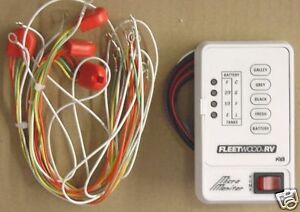
One thing I did figure out is that the current system consists of a single wire to each tank monitor, along with a ground wire.
The existing harness shown below has internal resistors, that I assume create a simple resistor-ladder network. I'm guessing the resistors are within the little red "puck".

If this is simply a resistor ladder network, the I am assuming the wire going to the monitor is connected to perhaps a pull-up resistor to +VCC and a transistor, opamp, etc is acting as a differential amp to light the correct LEDs. Of course this is conjecture on my part, but I'll probably be able to figure out more when I get the monitor.
When I ordered the foil capacitive sensor, I talked to the company, and there are three wires; +VCC, ground, and an analog signal wire. They told me that the signal wire is not encoded or digital, but rather an analog voltage between 0v when empty, and approx 5V when the tank is full. The actual voltage will vary depending on the height of the tank/length of the sensor strip.
In the simplest approach, I am thinking that the output of the sensor can go through an OpAmp configured as an amplifier with an adjustable gain, so the sensor can be calibrated to the monitor. The output of the OpAmp could go to a opto-isolator, with the output transistor's collector going to the pull up resistor in the monitor - if indeed that is how it works. The opto-isolator would also keep the OEM panel (somewhat) immune from the modified sensor.
Again, a lot of speculation here, but it should not be too difficult to achieve.
I originally thought of using an Arduino board as I have used them quite a bit, and I keep the monitor panel stock looking, I can use the existing LEDs which are OK in my view, if they were accurate. I have several Ardunio Uno boards laying around my shop.
But if the circuit is a simple ladder resistive network, a OpAmp and OptoIsolator would be simpler than the Arduino solution.
However, my thoughts were to use the capacitive sensor from New Providence, but if you want to make your own, then the Arduino solution might work best. At any rate, an Arduino UNO might be overkill.
__________________
The only thing that works on a RV is the owner...
|
|
|
|
|
02-26-2015, 04:04 PM
|
#4
|
|
Moderator Emeritus
Brand: Thor Motor Coach
Model: 2011 Four Winds 28Z
State: Michigan
Posts: 1,273
THOR #531
|
If my conjecture is correct, the original sensor circuit might look like this:

And if so, a possible interface circuit might look like this:

The only issue as I hinted in the other thread is how to turn the sensor and interface circuit on and off. I suppose in the worst case scenario they could just be left on, as we're probably only talking a few mA drain, so it should not significantly discharge the house batteries.
__________________
The only thing that works on a RV is the owner...
|
|
|
|
|
02-26-2015, 04:08 PM
|
#5
|
|
Moderator Emeritus
Brand: Thor Motor Coach
Model: 2011 Four Winds 28Z
State: Michigan
Posts: 1,273
THOR #531
|
I do have a monitor panel manual in PDF format. It does not go into a great amount of detail, but it does mention resistors in the wiring harness, and the connection to the monitor is a ground and single sensor wire.
I can send it to you if you want. PM me if so.
__________________
The only thing that works on a RV is the owner...
|
|
|
|
|
02-26-2015, 04:22 PM
|
#6
|
|
Axis/Vegas Enthusiast
Brand: Thor Motor Coach
Model: Axis 24.4
State: Michigan
Posts: 9,837
THOR #1150
|
The panel on our Axis looks different but I see its still a KiB one (logo at bottom left):

I will be interested to hear how the KiB panel is wired when you get it.
|
|
|
|
|
02-26-2015, 04:29 PM
|
#7
|
|
Axis/Vegas Enthusiast
Brand: Thor Motor Coach
Model: Axis 24.4
State: Michigan
Posts: 9,837
THOR #1150
|
Looking at the ladder network: Presumably the resistor values are chosen high enough that as the level rises the fluid shorts out successive resistors in the ladder.
Thus the voltage at the sensor point is: (assuming equal values for R--it is likely they would pick better values to separate the voltage levels better)
12*3*R/4*R (or just 3/4 of 12V) for empty (9V)
12*2/3 for 1/3 full (8V)
12*1/2 for 2/3 full (6V)
and ground for full (0V)
|
|
|
|
|
02-26-2015, 04:58 PM
|
#8
|
|
Moderator Emeritus
Brand: Thor Motor Coach
Model: 2011 Four Winds 28Z
State: Michigan
Posts: 1,273
THOR #531
|
The panel on your Axis is identical to my 28Z (except for the blank covers over the tank heater switches on my panel ).
I bought the one on eBay assuming the monitor uses the same technology. It has the same resistor ladder network cable and well nuts, and is made by the same company.
The foil sensor looks like this:
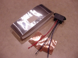
I got a good price on them $20. But they are normally $35. I don't know if they charged me $20 just because of being a repeat customer, or if they are interested in my idea of using their sensors for the monitor. I figured for $20, it was not worth trying to come up with my own.
__________________
The only thing that works on a RV is the owner...
|
|
|
|
|
02-26-2015, 05:08 PM
|
#9
|
|
Moderator Emeritus
Brand: Thor Motor Coach
Model: 2011 Four Winds 28Z
State: Michigan
Posts: 1,273
THOR #531
|
Here is where you can download the Manual.
http://dutchmen.com/media/6104/kib-e...nformation.pdf
Its surprising that Dutchmen still has it's own website. Wasn't Dutchmen acquired by Four Winds, then Thor? Or did someone else retain the name trademark?
__________________
The only thing that works on a RV is the owner...
|
|
|
|
|
02-26-2015, 05:12 PM
|
#10
|
|
Moderator Emeritus
Brand: Thor Motor Coach
Model: 2011 Four Winds 28Z
State: Michigan
Posts: 1,273
THOR #531
|
I just answered my own question. Seems Dutchmen is indeed a Thor company, but perhaps they are a still somewhat independent operation (but still located in NW Indiana).
__________________
The only thing that works on a RV is the owner...
|
|
|
|
|
02-26-2015, 07:54 PM
|
#11
|
|
Moderator Emeritus
Brand: Thor Motor Coach
Model: 2011 Four Winds 28Z
State: Michigan
Posts: 1,273
THOR #531
|
Dang that was fast, I received the monitor in the mail today. Northern Indiana parts surplus...

Looks fairly simply. I have not examined the circuit board yet, but it consists of a single LM339, which is a general purpose single supply quad voltage comparator OpAmp, a 2N3904 general purpose NPN transistor, and a handful of resistors and diodes.
Without tracing out the circuit, I am confident my initial hypothesis on how the circuit operates is correct...

And here is the harness which should have three resistors in it. Over the next couple of days, I'll figure out a schematic and values.
It is not a sophisticated circuit by any means.
I'm gonna download a datasheet on the LM339. With any luck, their circuit will be right out of the book.
__________________
The only thing that works on a RV is the owner...
|
|
|
|
|
02-26-2015, 08:04 PM
|
#12
|
|
Axis/Vegas Enthusiast
Brand: Thor Motor Coach
Model: Axis 24.4
State: Michigan
Posts: 9,837
THOR #1150
|
I'm guessing each comparator is used for a single LED and each is set to a different voltage threshold. Yup super simple!
In addition I bet each button runs its signal through a divider so that each input is scaled to the same levels (thus the comparisons on the comparators can be the same for each input).
|
|
|
|
|
02-26-2015, 08:39 PM
|
#13
|
|
Moderator Emeritus
Brand: Thor Motor Coach
Model: 2011 Four Winds 28Z
State: Michigan
Posts: 1,273
THOR #531
|
I am sure you are correct.
I hate to trace circuit boards though, but it appears that only three comparators are used. The output of each comparator goes to one of the three top LEDs. The bottom LED appears to always be ON, which corresponds to EMPTY.
__________________
The only thing that works on a RV is the owner...
|
|
|
|
|
02-26-2015, 09:01 PM
|
#14
|
|
Moderator Emeritus
Brand: Thor Motor Coach
Model: 2011 Four Winds 28Z
State: Michigan
Posts: 1,273
THOR #531
|
So far, this is what I have resolved:

Sure enough, it seems to be shaping up to be a simple resistor ladder network.
__________________
The only thing that works on a RV is the owner...
|
|
|
|
|
02-26-2015, 09:49 PM
|
#15
|
|
Axis/Vegas Enthusiast
Brand: Thor Motor Coach
Model: Axis 24.4
State: Michigan
Posts: 9,837
THOR #1150
|
Well you shouldn't have to trace out the entire circuit. Just some key points (like figuring out the resistance values in the ladder) and determining if the ladder is powered all the time (at least for my edification LOL).
|
|
|
|
|
02-26-2015, 10:23 PM
|
#16
|
|
Moderator Emeritus
Brand: Thor Motor Coach
Model: 2011 Four Winds 28Z
State: Michigan
Posts: 1,273
THOR #531
|
Yea, that is probably enough.
__________________
The only thing that works on a RV is the owner...
|
|
|
|
|
02-26-2015, 11:10 PM
|
#17
|
|
Moderator Emeritus
Brand: Thor Motor Coach
Model: 2011 Four Winds 28Z
State: Michigan
Posts: 1,273
THOR #531
|
I took some resistance readings of the harness and I finally got to put that Turing Machines course I had to take in college those many years ago to use.
This is what I came up with so far:

This is turning out to be about as basic as it can get.
One strange thing though, I did an ohms test both ways (swapping plus and minus test leads), and I was getting different readings, which suggested the possibility of a diode. But I was getting low readings in one direction, and slightly higher readings in another. This does not quite act like a diode, unless it has a very low PIV... but I never heard of a diode with a 1.5V PIV.
Since I had 4 harnesses (the monitor I bought is a 4 channel monitor) and I only need one channel for testing, I did some destructive testing and tore a harness apart, and sure enough, I confirmed my schematic was correct.
There was no diode, and after I tore the wires out of the potting compound, the goofy readings I was getting by reversing the test leads went away. I can only surmise that the potting compound they use must be very low quality.
The potting compound seems a bit strange and kind of rubbery feeling too. It was kind of like cutting into a bar of soap. Potting compound is usually made of epoxy and very brittle and hard to cut.
Now all I need to do is to figure out how this sets up with the input to the comparators, and if the switches turn on the entire system or just the ladder.
The manual states that the system draws no power unless a button is depressed, so I want to look into that as well.
__________________
The only thing that works on a RV is the owner...
|
|
|
|
|
02-26-2015, 11:29 PM
|
#18
|
|
Axis/Vegas Enthusiast
Brand: Thor Motor Coach
Model: Axis 24.4
State: Michigan
Posts: 9,837
THOR #1150
|
Wow! Great information. Thanks.
|
|
|
|
|
02-26-2015, 11:42 PM
|
#19
|
|
Moderator Emeritus
Brand: Thor Motor Coach
Model: 2011 Four Winds 28Z
State: Michigan
Posts: 1,273
THOR #531
|
Only thing I have not figured out yet is the resistance coefficient of p _ _ _.

Well, it is scientific analysis we're doing here...
__________________
The only thing that works on a RV is the owner...
|
|
|
|
|
02-27-2015, 12:20 AM
|
#20
|
|
Axis/Vegas Enthusiast
Brand: Thor Motor Coach
Model: Axis 24.4
State: Michigan
Posts: 9,837
THOR #1150
|
I bet you can just use a glass of water since the level system is supposed to work with all the tanks (fresh, black, and grey).
|
|
|
|
|
|
 Posting Rules
|
You may not post new threads
You may not post replies
You may not post attachments
You may not edit your posts
HTML code is Off
|
|
|
|
|


 Linear Mode


