I still do not understand why the proposed 30A receptacle in the electrical bay.

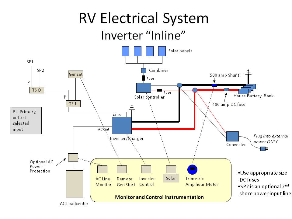
This diagram I borrowed from
John Mayer and it includes a solar application for your Stage 2.
This application is for a 'whole house' inverter, where everything AC will be powered by the inverter. The only "odd" item I see is there are two shore power cords (for his 5th wheel by what I understand), you only have to use one. There is also shown the OEM converter... it is there to only be connected externally, to eliminate all confusion, like an emergency back-up.
So when you have AC power from either the SP cable plugged into a pedestal or the generator is running, the TS1 transfer switch (OEM) will supply the inverter. The inverter will use that AC and
1) Convert the AC to DC for charging the batteries.
2) Bypass the inverter part with its internal transfer switch and supply the RVs AC breaker panel.
Now, if the TS1 fails, there is no generator power AND/or the shore power cable has no AC to it, the inverter will do its job.
1) No AC to the input of the inverter, the inverter now turns off the battery charger (internal)
2) The internal inverter transfer switch connects the inverter part to the AC breaker panel
3) The inverter starts humming and supplies pure sine wave power (in your case). 
Maybe the John Mayer link will help. So why the 30A receptacle?
 Thor Forums

