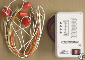
This is exactly what I have been thinking about. In fact, I did order a monitor panel from eBay along with the well-nuts:
Also, I ordered a foil sensor from "New Providence Marine" as the replacement sensor.
Perhaps we can collaborate a bit as a joint venture.
One thing I did figure out is that the current system consists of a single wire to each tank monitor, along with a ground wire.
The existing harness shown below has internal resistors, that I assume create a simple resistor-ladder network. I'm guessing the resistors are within the little red "puck".

If this is simply a resistor ladder network, the I am assuming the wire going to the monitor is connected to perhaps a pull-up resistor to +VCC and a transistor, opamp, etc is acting as a differential amp to light the correct LEDs. Of course this is conjecture on my part, but I'll probably be able to figure out more when I get the monitor.
When I ordered the foil capacitive sensor, I talked to the company, and there are three wires; +VCC, ground, and an analog signal wire. They told me that the signal wire is not encoded or digital, but rather an analog voltage between 0v when empty, and approx 5V when the tank is full. The actual voltage will vary depending on the height of the tank/length of the sensor strip.
In the simplest approach, I am thinking that the output of the sensor can go through an OpAmp configured as an amplifier with an adjustable gain, so the sensor can be calibrated to the monitor. The output of the OpAmp could go to a opto-isolator, with the output transistor's collector going to the pull up resistor in the monitor - if indeed that is how it works. The opto-isolator would also keep the OEM panel (somewhat) immune from the modified sensor.
Again, a lot of speculation here, but it should not be too difficult to achieve.
I originally thought of using an Arduino board as I have used them quite a bit, and I keep the monitor panel stock looking, I can use the existing LEDs which are OK in my view, if they were accurate. I have several Ardunio Uno boards laying around my shop.
But if the circuit is a simple ladder resistive network, a OpAmp and OptoIsolator would be simpler than the Arduino solution.
However, my thoughts were to use the capacitive sensor from New Providence, but if you want to make your own, then the Arduino solution might work best. At any rate, an Arduino UNO might be overkill.
 Thor Forums

